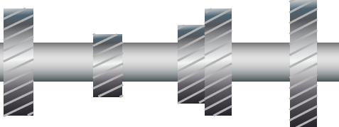
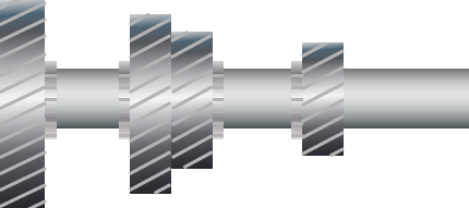
How Vehicle Gearboxes Work

Gearboxes - The Basics

What Is A Gearbox?

a hand drawn illustration of a typical vehicle gearbox with the side casing removed showing all the gears and shafts

A Gearbox is typically enclosed in a aluminium alloy casing a collection of connecting shafts and gears submersed in oil for lubrication and cooling.

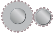
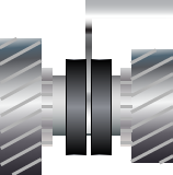
What Does A Gearbox Do?

Facilitates the varying of torque and speed on the box output shaft with reference to the input shaft. See our superb manual vehicle gearbox animation to see a gearbox in action.

Everything Your Gearbox Does
  • Varies the torque on the output shaft
  • Varies the speed of the output shaft
  • Provides a reverse gear
  • Disconnects and connects drive between the clutch and the differential
  • Provides an overdrive gear which rotates the output shaft more per turn than the input shaft, usually for fuel economy

Gearbox Shafts

Input Shaft

1 shaft with 1 gear

The gearbox input shaft is considerably shorter than the output shaft and fixed to its gear. It is responsible for transferring drive from the vehicle engine assuming engaged through the clutch system into the gearbox. Here its gear drives the connecting layshaft gear and thus drives the layshaft. There is no selector here and as such the input shaft permanently drives the layshaft. Pressing the drivers clutch pedal disconnects drive from the input shaft and consequently the layshaft.

Lay Shaft

layshaft with 5 various size gears

The lay shaft is fixed to its gears and is driven at a constant speed by the engine regardless of the gear the gearbox is in including reverse or neutral. The clutch (operated by the drivers foot pedal) enables the lay shaft speed to be independent of the engine by utilising a friction taper or similar to press up against a gear to make the gear rotate at the same speed forcing the lay shaft to change accordingly.

Output Shaft

mainshaft with 4 various size gears

The output shaft is not fixed to its gears. The gearbox output shaft is a simple splined shaft that is connected to its gears only via the dog clutches, as the gears themselves are not splined. The output shaft’s speed relative to the countershaft is determined by the ratio of the two gears: the one permanently attached to the countershaft, and that gear’s mate which is now locked to the output shaft.

Gearbox Gears

What Are All those Gears For?

1 shaft with 1 gear

Gears are used for transmitting power from one gearbox shaft to another and to either increase, decrease or maintain speed and torque. Note that a speed increase results in a decrease in torque and a torque increase results in a decrease in speed. A Manual gearbox is designed with selectable pairs of gears that can be engaged and locked together to the output shaft. These are our driving gears with fixed gear ratios. All the gears turn relative to the lay shaft.

Typical Gear Ratios

1st Gear
1 large gear and the smallest gear gives us 1st gear
2nd Gear
1 large gear and the 2nd smallest gear up gives us 2nd gear
3rd Gear
1 large gear and the 2nd largest gear make up 3rd gear
4th Gear
1 large gear and the largest gear make up 4th gear

What Are Gear Ratios?

Vehicle manufacturers determine gear ratios based on the vehicles purpose & specification but typically 1st gear is the slowest gear with a ratio of 3.2 to 1 but provides maximum torque to get the vehicle moving from a standing start or to climb a steep hill. The vehicles 2nd gear helps build speed whilst providing lots of torque due to the gear reduction (2.1:1). The gearboxes 3rd gear again helping build speed with a ratio of 1.3 to 1 now providing much less torque then 1st and less than 2nd gear. 4th gear is usually locked to the output shaft so has a ratio of one to one (1:1) and transfers the same speed and torque from the input shaft to the output shaft. Our 4th gear is an overdrive gear and has a ratio of (1:1.7). This means for every turn of the input shaft the output shat turns 1.7 times. This is how we get our maximum fuel economy.

Synch & Change

Dog Clutch

gearbox dog clutch consisting of a sliding collar which slides and locks gears to the shaft

The dog clutch is responsible for locking the output shaft with a gear by a sliding selector. The dog clutch hub has teeth on its inner that fit in splines on the output shaft. To select a gear the dog clutch is pushed by a selector fork that is linked to the gear lever allowing the dog clutch to slide either way on the shaft splines. When the dog clutch makes contact with the gear the synchroniser system spins up the selector and gear to the same speed. The output shaft now rotates.

Gear Selectors

gear selector inside a vehicle with a moveable gear nob attached to the selector forks

The gear selector does not engage or disengage the actual gear teeth which are permanently meshed. The action of the gear selector is to lock one of the freely spinning gears to the shaft that runs through its hub. The shaft then spins together with that gear. The fork does not rotate, so it is attached to a collar bearing on the selector. The selector is typically symmetric: it slides between two gears and has a synchromesh and teeth on each side in order to lock either gear to the shaft..

Synchromesh System

synchromesh system showing how the gearbox synchromesh synchronises the 2 gears before the gear is selected

When the dog teeth make contact with the gear the two parts are spinning at different speeds. Without the use of a synchoniser system or synchromesh the teeth would not engage correctly and create a loud grinding sound. A simple synchroniser mechanism or synchromesh cone clutch first makes contact with the gear and uses friction to synchronise the selector and gear speed. Before speed synchronisation the teeth are prevented from coming together by use of a blocker (or baulk) ring. At the point of synchronisation the blocker ring twists slightly as friction resides aligning grooves or notches allowing the selector and teeth to correctly engage.

Telephone 0114 2363617 Scroll To Top